2006 Saturn Ion Fuse Diagram
- Category : Fuse Diagram
- Post Date : January 27, 2026
2006 Saturn Ion Fuse Diagram
Fuse Box Diagram U0026gt Saturn Ion 2003

2003
Fuse Box Diagram U0026gt Saturn Ion 2003

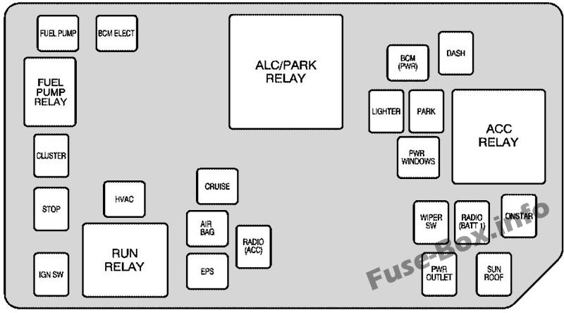
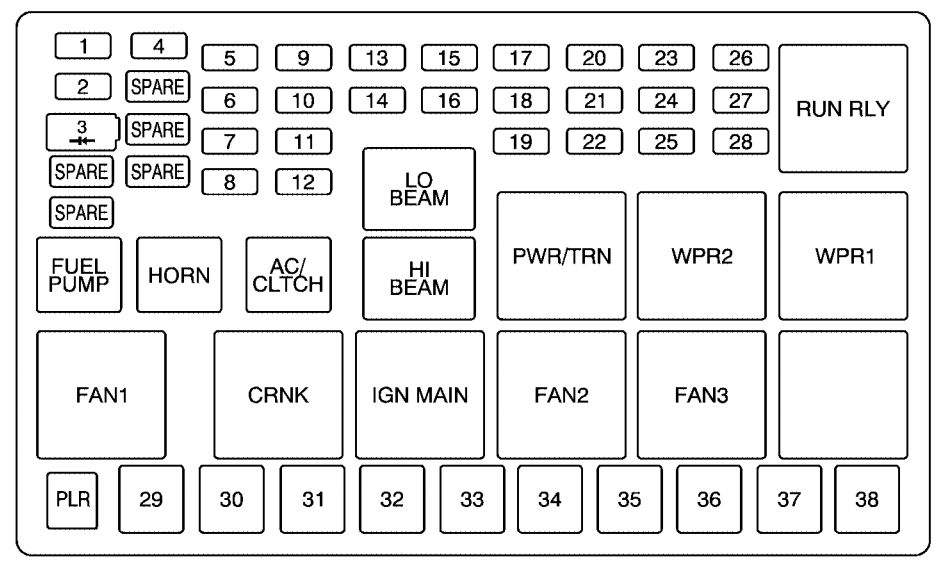
2006 Saturn Ion Fuse Box

I Have A 2004 Saturn Ion And The Cigarette Lighter And
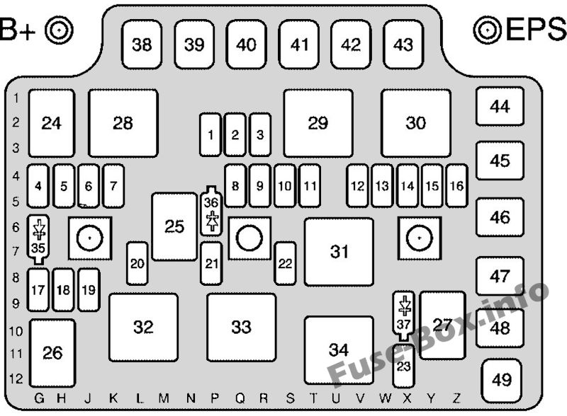
Saturn Ion 2003 - 2004 - Fuse Box Diagram

Diagram 2007 Saturn Ion Fuse Box Diagram
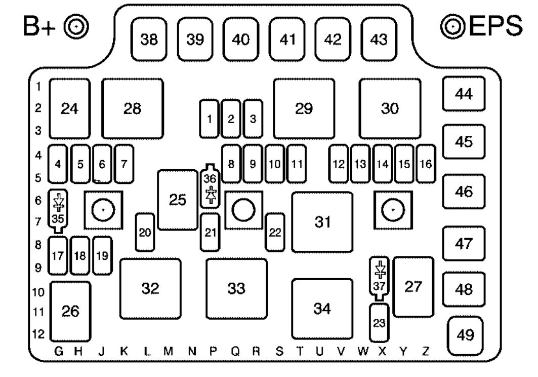
Saturn Ion 2003 - 2004 - Fuse Box Diagram

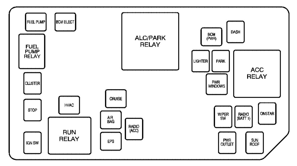
2006 Saturn Ion Fuse Box

2006 Saturn Ion Fuse Box

2007 Saturn Ion Fuse Diagram
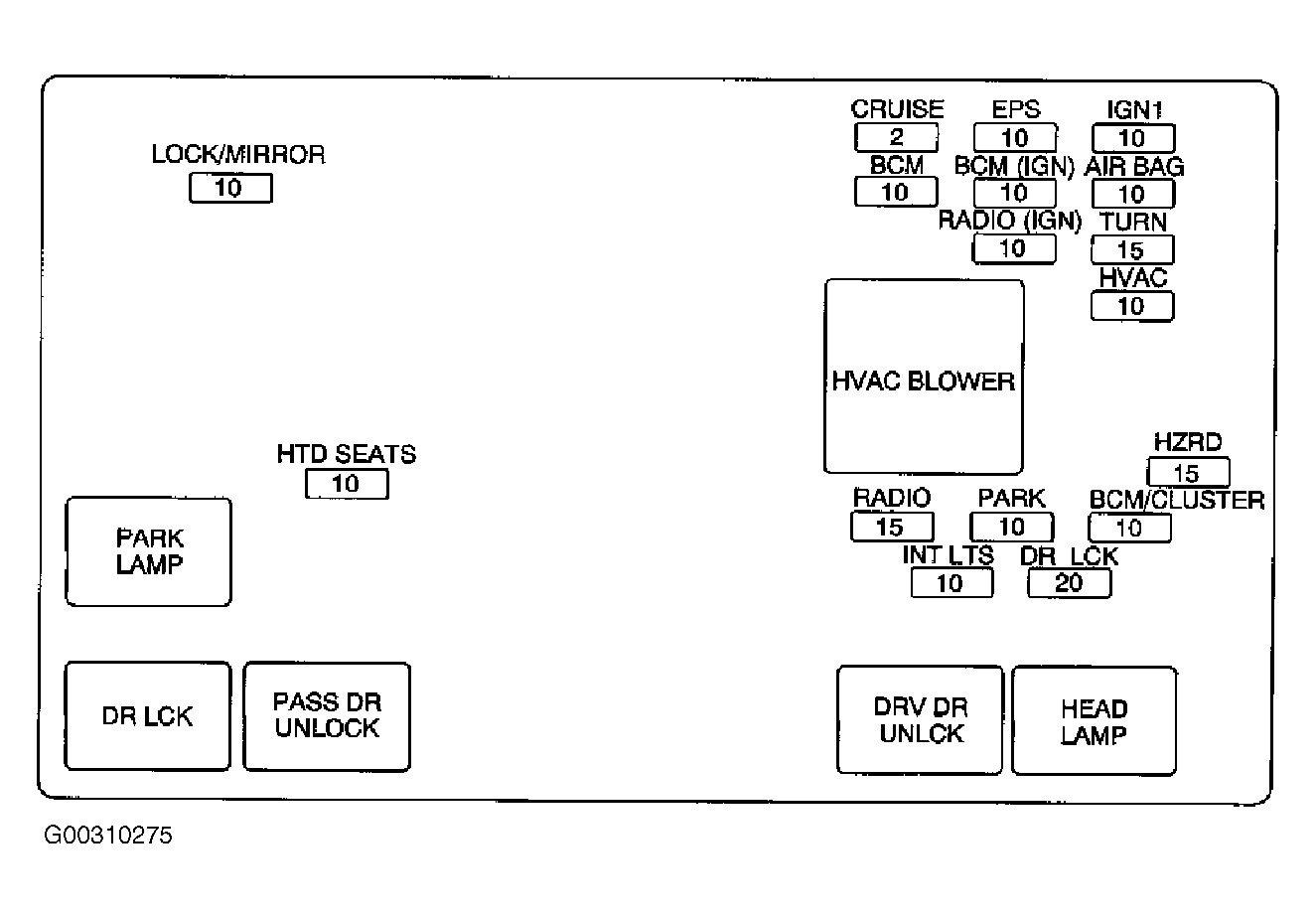
2006 Saturn Ion Fuse Box Diagram

2003 Saturn Ion 2 Fuse Box Diagram

2006 Saturn Ion Fuse Box

05 Saturn Ion Fuse Box
Saturn Relay 2005 - Fuse Box Diagram

2003 Saturn Ion What Is Damaged By Hooking The Battery Up

2006 Saturn Ion Fuse Box Diagram

2006 Saturn Ion Fuse Box Diagram
2008 Saturn Vue Fuse Diagram

I Have A 2003 Saturn Ion All Of A Sudden The Button To

04 Saturn Ion Fuse Box Diagram

I Have A 04 Saturn Ion Coupe The L F Turn Signal Daytime

2003 Saturn Ion 2 Fuse Box Diagram

2004 Saturn Ion Engine Diagram

Solved I Need A Wiring Diagram For A 2004 Saturn Ion

Solved I Need A Wiring Diagram For A 2004 Saturn Ion

Fuse Box For 2005 Saturn Ion

Solved I Need A Wiring Diagram For A 2004 Saturn Ion

2004 Saturn Ion Will Not Crank The Battery Is Good And

Saturn Vue Wiring Diagram

Can You Please Tell Me What Would Most Likely Be Causing

I Did It Well Kind Of

2006 Saturn Ion Fuse Box Diagram
Diagram 2006 Saturn Ion Fuse Diagram
Download 2006 Saturn Ion Fuse Diagram
This combinational device has 2^n inputs, n select lines, and one output. When the circuit receives an n bit value on its select lines, the output takes on the value carried by the input that corresponds to the select value.
This synchronous sequential device consists of n commonly clocked and commonly controlled flip flops. On successive clock cycles, it moves through a predetermined order of n bit states.
This combinational device has 2 inputs, n select lines, and one output. When the circuit receives an n bit value on its select lines, the output takes on the value carried by the input that corresponds to the select value.
When exactly one of the inputs is asserted, the outputs take on a corresponding n bit value. When more than one of the inputs is asserted, the output takes on an n bit value that corresponds to whichever one of the asserted inputs has precedence over the other asserted inputs.
A binary decoder is used when you need to activate exactly one of 2n outputs based on an n bit input value. Table 1 is the truth table of a 2 to 4 decoder. The input code word I1,I0 represents an integer in the range 0–3.
A binary encoder encodes data from 2n inputs into an n bit code. Exactly one of the input lines should have a value of 1, i.e. the input should be one hot encoded data.
This combinational device has 2n inputs, n select lines, and one output. When the circuit receives an n bit value on its select lines, the output takes on the value carried by the input that corresponds to the select value.
A device consisting of n commonly clocked and commonly controlled flip flops that has the capability (perhaps among others) to move the bits that make up its n bit state in one direction
Though the other inputs with smaller subscripts, namely, E2, E1, and E0 are also having values of one in some combinations, but they do not have the priority. The truth table can be rewritten in a more compact form using don’t care conditions for inputs as shown below in table 9.
This combinational device has 2n inputs and n outputs. When exactly one of the inputs is asserted, the outputs take on a corresponding n bit value. Your solution’s ready to go! Enhanced with AI, our expert help has broken down your problem into an easy to learn solution you can count on.
3 way switch,3 way switch wiring,3 way switch wiring diagram pdf,3 way wiring diagram,3way switch wiring diagram,4 prong dryer outlet wiring diagram,4 prong trailer wiring diagram,6 way trailer wiring diagram,7 pin trailer wiring diagram with brakes,7 pin wiring diagram,alternator wiring diagram,amp wiring diagram,automotive lighting,cable harness,chevrolet,diagram,dodge,doorbell wiring diagram,ecobee wiring diagram,electric motor,electrical connector,electrical wiring,electrical wiring diagram,ford,fuse,honeywell thermostat wiring diagram,ignition system,kenwood car stereo wiring diagram,light switch wiring diagram,lighting,motor wiring diagram,nest doorbell wiring diagram,nest hello wiring diagram,nest labs,nest thermostat,nest thermostat wiring diagram,phone connector,pin,pioneer wiring diagram,plug wiring diagram,pump,radio,radio wiring diagram,relay,relay wiring diagram,resistor,rj45 wiring diagram,schematic,semi-trailer truck,sensor,seven pin trailer wiring diagram,speaker wiring diagram,starter wiring diagram,stereo wiring diagram,stereophonic sound,strat wiring diagram,switch,switch wiring diagram,telecaster wiring diagram,thermostat wiring,thermostat wiring diagram,trailer brake controller,trailer plug wiring diagram,trailer wiring diagram,user guide,wire,wire diagram,wiring diagram,wiring diagram 3 way switch,wiring harness
